[CUBEMAPS]
1. Cubemaps
- 여러 texture들을 하나의 texture로 매핑한, 기본적으로 cube의 각 면을 형성하는 2D texture들을 포함하고 있는 texture
- cubemap을 사용하면 방향 vector를 사용하여 인덱싱/샘플링될 수 있다
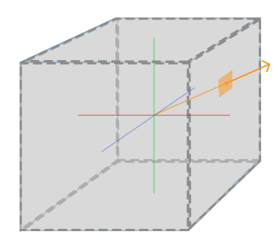
- cubemap으로부터 texture를 샘플링하는 것은 좌측의 그림처럼 보인다
: 주황색 vector는 방향 vector로, 이것의 크기는 상관없다
: 방향 vector의 방향만 제공된다면 OpenGL이 방향과 맞닿는 해당 texel을 얻고,
적절히 샘플링된 texture 값을 return 한다
- 이러한 cubemap을 첨부한 큐브 도형을 가지고 있다면 이 cubemap을 샘플링하는 방향 vector는 cube의 보간된 vertex 위치와 비슷하다
- 이 방법으로 이 큐브가 원점에 존재한다면 이 큐브의 실제 위치 vector들을 사용하여 cubemap을 샘플링할 수 있다
: 이후 큐브의 vertex 위치를 texture coordinate로서 얻을 수 있다
- 결과적으로 cubemap의 적절한 각 face를 접근할 수 있는 texture coordinate를 얻을 수 있다
2. Creating A Cubemap
unsigned int textureID;
glGenTextures(1, &textureID);
glBindTexture(GL_TEXTURE_CUBE_MAP, textureID);
- cubemap은 다른 texture들과 같은 texture이므로 생성하기 위해서 texture 연산을 실행하기 전에, texture를 생성하고 적절한 texture target에 바인딩한다
: 이번에는 GL_TEXTURE_CUBE_MAP에 바인딩한다
- cubemap은 6개의 texture로 이루어져있기 떄문에 glTexImage2D 함수를 6번 호출해얗나다
: 이 함수는 저번과 동일하게 사용하지만 texture target parameter에 cubemap의 특정 face(면)를 설정한다
: 이는 우리가 cubemap의 각 면마다 glTexImage2D 함수를 호출해야한다는 것을 의미한다
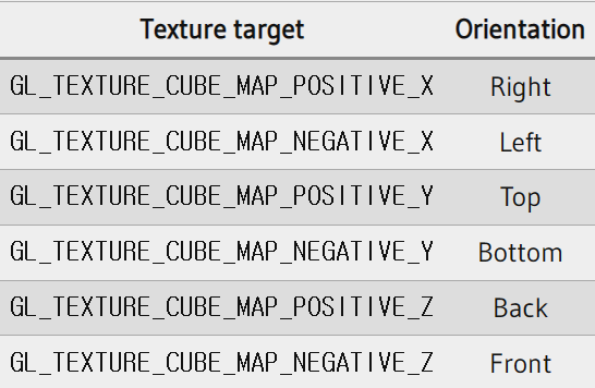
- 6개의 면을 가지고 있기 때문에 OpenGL은 cubemap의 면들을 타겟팅할 수 있도록 6개의 texture target을 제공한다
int width, height, nrChannels;
unsigned char *data;
for(unsigned int i = 0; i < textures_faces.size(); i++)
{
    data = stbi_load(textures_faces[i].c_str(), &width, &height, &nrChannels, 0);
    glTexImage2D(
        GL_TEXTURE_CUBE_MAP_POSITIVE_X + i,
        0, GL_RGB, width, height, 0, GL_RGB, GL_UNSIGNED_BYTE, data
    );
}
- 다른 OpenGL의 enum 변수들과 마찬가지로 이 texture target은 점점 연속적으로 증가하는 int형 변수다
: texture의 vector 배열을 가지고 있다면 이들을 반복문으로 돌려 GL_TEXTURE_CUBE_MAP_POSITIVE_X로 시작하여 이 변수를 1씩 증가시켜가면서 효율적으로 모든 texture target들을 설정할 수 있다
- textures_face vector는 cubemap을 위한 모든 texture의 위치를 위 표의 순서대로 가지고 있는 vector다
: 이는 현재 바인딩된 cubemap의 각 면에 texture를 생성한다
glTexParameteri(GL_TEXTURE_CUBE_MAP, GL_TEXTURE_MAG_FILTER, GL_LINEAR);
glTexParameteri(GL_TEXTURE_CUBE_MAP, GL_TEXTURE_MIN_FILTER, GL_LINEAR);
glTexParameteri(GL_TEXTURE_CUBE_MAP, GL_TEXTURE_WRAP_S, GL_CLAMP_TO_EDGE);
glTexParameteri(GL_TEXTURE_CUBE_MAP, GL_TEXTURE_WRAP_T, GL_CLAMP_TO_EDGE);
glTexParameteri(GL_TEXTURE_CUBE_MAP, GL_TEXTURE_WRAP_R, GL_CLAMP_TO_EDGE);
- Cubemap은 다른 texture들과 다를 게 없기 때문에 wrapping, filtering method를 지정할 수 있다
- GL_TEXTURE_WARP_R은 단순히 texture의 3번째 차원에 해당하는 R좌표에 대한 warpping method를 지정한다
- GL_CLAMP_TO_EDGE를 사용하여 정확히 두 면 사이에 있는 texture coordinate들이 정확한 면을 가리키지 않을 때를 대비해 면 사이를 샘플링할 때마다 OpenGL이 항상 그들의 모서리 값을 return하도록 한다
- 이후 cubemap을 사용할 object를 그리기 전에 해당 texture unit을 활성화하고 렌더링하기 전에 cubemap을 바인딩한다
in vec3 textureDir; // direction vector representing a 3D texture coordinate
uniform samplerCube cubemap; // cubemap texture sampler

void main()
{
    FragColor = texture(cubemap, textureDir);
}
- Fragment shader 내부에서 우리는 다른 샘플러 타입인 sameplerCube를 사용한다
: 이 타입은 texture 함수를 사용하여 샘플링하는 것은 동일하지만, vec2 대신에 vec3의 방향 vector를 사용한다
[SKYBOX]
1. Loading A Skybox
unsigned int loadCubemap(vector<std::string> faces)
{
    unsigned int textureID;
    glGenTextures(1, &textureID);
    glBindTexture(GL_TEXTURE_CUBE_MAP, textureID);

    int width, height, nrChannels;
    for (unsigned int i = 0; i < faces.size(); i++)
    {
        unsigned char *data = stbi_load(faces[i].c_str(), &width, &height, &nrChannels, 0);
        if (data)
        {
            glTexImage2D(GL_TEXTURE_CUBE_MAP_POSITIVE_X + i,
                         0, GL_RGB, width, height, 0, GL_RGB, GL_UNSIGNED_BYTE, data
            );
            stbi_image_free(data);
        }
        else
        {
            std::cout << "Cubemap tex failed to load at path: " << faces[i] << std::endl;
            stbi_image_free(data);
        }
    }
    glTexParameteri(GL_TEXTURE_CUBE_MAP, GL_TEXTURE_MIN_FILTER, GL_LINEAR);
    glTexParameteri(GL_TEXTURE_CUBE_MAP, GL_TEXTURE_MAG_FILTER, GL_LINEAR);
    glTexParameteri(GL_TEXTURE_CUBE_MAP, GL_TEXTURE_WRAP_S, GL_CLAMP_TO_EDGE);
    glTexParameteri(GL_TEXTURE_CUBE_MAP, GL_TEXTURE_WRAP_T, GL_CLAMP_TO_EDGE);
    glTexParameteri(GL_TEXTURE_CUBE_MAP, GL_TEXTURE_WRAP_R, GL_CLAMP_TO_EDGE);

    return textureID;
}
- skybox는 그 자체로 단지 cubemap이기 때문에 skybox를 불러오는 것을 이전과 크게 다르지 않다
: skybox를 불러오기 위해 6개의 texture 위치를 가지고 있는 vector를 받아들이는 함수를 사용한다
vector<std::string> faces;
{
    "right.jpg",
    "left.jpg",
    "top.jpg",
    "bottom.jpg",
    "front.jpg",
    "back.jpg"
};
unsigned int cubemapTexture = loadCubemap(faces);
- 위 함수를 호출하기 전에 적절한 texture 경로를 vector에 불러온다
2. Displaying a Skybox
float skyboxVertices[] = {
    // positions
    -1.0f,  1.0f, -1.0f,
    -1.0f, -1.0f, -1.0f,
     1.0f, -1.0f, -1.0f,
     1.0f, -1.0f, -1.0f,
     1.0f,  1.0f, -1.0f,
    -1.0f,  1.0f, -1.0f,

    -1.0f, -1.0f,  1.0f,
    -1.0f, -1.0f, -1.0f,
    -1.0f,  1.0f, -1.0f,
    -1.0f,  1.0f, -1.0f,
    -1.0f,  1.0f,  1.0f,
    -1.0f, -1.0f,  1.0f,

     1.0f, -1.0f, -1.0f,
     1.0f, -1.0f,  1.0f,
     1.0f,  1.0f,  1.0f,
     1.0f,  1.0f,  1.0f,
     1.0f,  1.0f, -1.0f,
     1.0f, -1.0f, -1.0f,

    -1.0f, -1.0f,  1.0f,
    -1.0f,  1.0f,  1.0f,
     1.0f,  1.0f,  1.0f,
     1.0f,  1.0f,  1.0f,
     1.0f, -1.0f,  1.0f,
    -1.0f, -1.0f,  1.0f,

    -1.0f,  1.0f, -1.0f,
     1.0f,  1.0f, -1.0f,
     1.0f,  1.0f,  1.0f,
     1.0f,  1.0f,  1.0f,
    -1.0f,  1.0f,  1.0f,
    -1.0f,  1.0f, -1.0f,

    -1.0f, -1.0f, -1.0f,
    -1.0f, -1.0f,  1.0f,
     1.0f, -1.0f, -1.0f,
     1.0f, -1.0f, -1.0f,
    -1.0f, -1.0f,  1.0f,
     1.0f, -1.0f,  1.0f
};
- Skybox는 cube 위에 그려지기 때문에 우리는 또다른 VAO, VBO가 필요하고 다른 object와 마찬가지로 vertex data 세트가 필요하다
- 3D cube의 texture로 사용되는 cubemap은 cube의 위치를 texture coordinate로 사용하여 샘플링할 수 있다
: cube가 원점에 위치해있을 때 위치 vector들은 원점으로부터의 방향 vector와 동일하며, 방향 vector는 해당 texture값을 얻기위해 필요하다
: 따라서 우리는 오직 위치 vector만 제공하면 되고, texture coordinate는 필요하지 않다
#version 330 core
layout (location = 0) in vec3 aPos;

out vec3 TexCoords;

uniform mat4 projection;
uniform mat4 view;

void main()
{
    TexCoords = aPos;
    gl_Position = projection * view * vec4(aPos, 1.0);
}
- skybox를 렌더링하기 위해 새로운 shader 세트가 필요하다
: 우리는 오직 하나의 vertex attribute만 필요하므로 vertex shader는 간단하다
#version 330 core
out vec4 FragColor;

in vec3 TexCoords;

uniform samplerCube skybox;

void main()
{
    FragColor = texture(skybox, TexCoords);
}
- vertex shader가 입력 받은 위치 vector를 fragment shader로 보낼 texture coordinate로 출력하면 fragment shdaer는 이를 입력받아 samplerCube를 샘플링한다
- fragment shdaer는 vertex attribute의 위치 vector를 texture의 방향 vector로 취하고 이것들을 cubemap으로부터 texture 값을 샘플링하기 위해 사용한다
glDepthMask(GL_FALSE);
skyboxShader.use();
// ... set view and projection matrix
glBindVertexArray(skyboxVAO);
glBindTexture(GL_TEXTURE_CUBE_MAP, cubemapTexture);
glDrawArrays(GL_TRIANGLES, 0, 36);
glDepthMask(GL_TRUE);
// ... draw rest of the scene
- 간단히 cubemap texture를 바인딩하면 이 skybox sampler는 자동적으로 sktybox cubemap으로 채워지게 된다
- skybox를 그리기 위해 가장 먼저 scene에 skybox를 그리고 depth 작성을 비활성화한다
: 이렇게 하면 skybox는 항상 모든 object들의 뒤에 그려지게 된다
glm::mat4 view = glm::mat4(glm::mat3(camera.GetViewMatrix()));- view matrix를 3x3 matrix로 변환한 후 다시 4x4 matrix로 변환하여 view matrix의 이동 부분을 없앤다
3. An Optimization
- 프로그램의 성능 향상을 위해 skybox를 제일 마지막에 렌더링할 것이다
: 이제 depth buffer는 완전히 다른 object들의 depth 값으로 채워지므로 우리는 early depth test를 통과한 skybox의 fragment들만 렌더링한다
: 위 방법을 사용하면 비약적으로 fragment shdaer 호출 횟수를 줄일 수 있으나 skybox는 1x1 cube이기 때문에 대부분 렌더링에 실패한다
- 따라서 우리는 depth buffer에 트릭을 써서 skybox가 depth 값을 최댓값인 1.0을 가지고 있다고 믿게 만들어 앞에 다른 object들이 있는 곳은 test에 실패하도록 해야한다
void main()
{
    TexCoords = aPos;
    vec4 pos = projection * view * vec4(aPos, 1.0);
    gl_Position = pos.xyww;
}
- 좌표 시스템 파트에서 perspective division이 vertex shader가 실행된 후에 gl_Position의 xyz coordinate를 w 요소로 나눔으로써 수행된다고 언급했었고, depth testing 파트에서는 나눗셈의 결과 z 요소는 vertex의 depth 값과 동일하다고 말했었다
: 이 정보를 사용하여 출력 위치의 z 요소를 w 요소와 동일하게 설정하여 z 값이 항상 1.0이 될 수 있도록 만들 수 있다
: perspective division이 수행될 떄 z 요소는 w/w=1.0 으로 변환되기 때문이다
- 결과 NDC 좌표는 depth 값의 최대치인 1.0의 z값을 가지게 된다
- 이 skybox는 결과적으로 오직 다른 object들이 없는 곳에서만 렌더링되게 된다 (skybox 앞에 있는 것들은 depth testing에서 통과한다)
- depth 함수를 기본값인 GL_LESS 대신에 GL_LEQUAL로 설정해야한다
- depth buffer는 skybox에 대해 1.0 값으로 채워지므로 skybox를 통과하게 만들기 위해 less than이 아닌 less than or equal로 수정해야한다
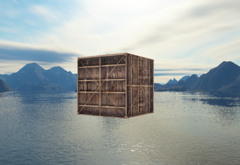
- 프로그램 실행 결과
[ENVIRONMENT MAPPING]
+) denvironment mapping : 환경 cubemap을 사용하는 기술로, 가장 많이 사용되는 것이 reflection과 refraction이다
1. Reflection
- reflection : object 또는 object의 특정 부분이 주변 환경을 반사하는 특성이다
- 시점의 각도를 기반으로 object의 컬러들은 환경과 동일하게 설정될 수 있다
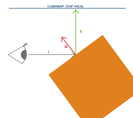
- 좌측의 이미지는 reflection vector를 계산하는 방법과 cubemap을 샘플링하기 위해 reflection vector를 사용하는 방법을 보여준다
- view 방향 vector I를 기반으로 object의 법선 vector N에 따른 반사 vector R을 계산한다
: GLSL의 reflect 함수를 사용하여 R을 계산할 수 있다
- R은 cubemap을 인덱싱/샘플링하기 위한 방향 vector로서 사용된다
: 최종 효과는 object가 skybox를 반사하는 것처럼 보일 것이다
#version 330 core
out vec4 FragColor;

in vec3 Normal;
in vec3 Position;

uniform vec3 cameraPos;
uniform samplerCube skybox;

void main()
{
    vec3 I = normalize(Position - cameraPos);
    vec3 R = reflect(I, normalize(Normal));
    FragColor = vec4(texture(skybox, R).rgb, 1.0);
}
- 컨테이너에 사용된 fragment shdaer를 수정해 반사 속성을 추가한다
: view/camera 방향 vector I를 계산하고 반사 vector R을 계산하기 위해 사용한다
#version 330 core
layout (location = 0) in vec3 aPos;
layout (location = 1) in vec3 aNormal;

out vec3 Normal;
out vec3 Position;

uniform mat4 model;
uniform mat4 view;
uniform mat4 projection;

void main()
{
    Normal = mat3(transpose(inverse(model))) * aNormal;
    Position = vec3(model * vec4(aPos, 1.0));
    gl_Position = projection * view * vec4(Position, 1.0);
}
- fragment의 보간된 Normal과 Position 변수를 가지고 있으므로 vertex shader 또한 수정해야한다
- 법선 vector를 사용하고 있으므로 단위 vector로 이들을 변환하고자 한다
- Position 출력 vector는 world-space 위치 vector다
: 이 Position 출력은 fragment shader에서 view 방향 vector를 계산하기 위해 쓰인다
float vertices[] = {
    -0.5f, -0.5f, -0.5f,  0.0f,  0.0f, -1.0f,
     0.5f, -0.5f, -0.5f,  0.0f,  0.0f, -1.0f,
     0.5f,  0.5f, -0.5f,  0.0f,  0.0f, -1.0f,
     0.5f,  0.5f, -0.5f,  0.0f,  0.0f, -1.0f,
    -0.5f,  0.5f, -0.5f,  0.0f,  0.0f, -1.0f,
    -0.5f, -0.5f, -0.5f,  0.0f,  0.0f, -1.0f,

    -0.5f, -0.5f,  0.5f,  0.0f,  0.0f, 1.0f,
     0.5f, -0.5f,  0.5f,  0.0f,  0.0f, 1.0f,
     0.5f,  0.5f,  0.5f,  0.0f,  0.0f, 1.0f,
     0.5f,  0.5f,  0.5f,  0.0f,  0.0f, 1.0f,
    -0.5f,  0.5f,  0.5f,  0.0f,  0.0f, 1.0f,
    -0.5f, -0.5f,  0.5f,  0.0f,  0.0f, 1.0f,

    -0.5f,  0.5f,  0.5f, -1.0f,  0.0f,  0.0f,
    -0.5f,  0.5f, -0.5f, -1.0f,  0.0f,  0.0f,
    -0.5f, -0.5f, -0.5f, -1.0f,  0.0f,  0.0f,
    -0.5f, -0.5f, -0.5f, -1.0f,  0.0f,  0.0f,
    -0.5f, -0.5f,  0.5f, -1.0f,  0.0f,  0.0f,
    -0.5f,  0.5f,  0.5f, -1.0f,  0.0f,  0.0f,

     0.5f,  0.5f,  0.5f,  1.0f,  0.0f,  0.0f,
     0.5f,  0.5f, -0.5f,  1.0f,  0.0f,  0.0f,
     0.5f, -0.5f, -0.5f,  1.0f,  0.0f,  0.0f,
     0.5f, -0.5f, -0.5f,  1.0f,  0.0f,  0.0f,
     0.5f, -0.5f,  0.5f,  1.0f,  0.0f,  0.0f,
     0.5f,  0.5f,  0.5f,  1.0f,  0.0f,  0.0f,

    -0.5f, -0.5f, -0.5f,  0.0f, -1.0f,  0.0f,
     0.5f, -0.5f, -0.5f,  0.0f, -1.0f,  0.0f,
     0.5f, -0.5f,  0.5f,  0.0f, -1.0f,  0.0f,
     0.5f, -0.5f,  0.5f,  0.0f, -1.0f,  0.0f,
    -0.5f, -0.5f,  0.5f,  0.0f, -1.0f,  0.0f,
    -0.5f, -0.5f, -0.5f,  0.0f, -1.0f,  0.0f,

    -0.5f,  0.5f, -0.5f,  0.0f,  1.0f,  0.0f,
     0.5f,  0.5f, -0.5f,  0.0f,  1.0f,  0.0f,
     0.5f,  0.5f,  0.5f,  0.0f,  1.0f,  0.0f,
     0.5f,  0.5f,  0.5f,  0.0f,  1.0f,  0.0f,
    -0.5f,  0.5f,  0.5f,  0.0f,  1.0f,  0.0f,
    -0.5f,  0.5f, -0.5f,  0.0f,  1.0f,  0.0f
};
- 법선을 사요하기 때문에 vertex data와 attribute pointer를 수정해야하고, cameraPos uniform도 설정해주어야한다
: 위 코드는 수정된 vertex data다
glBindVertexArray(cubeVAO);
glBindTexture(GL_TEXTURE_CUBE_MAP, skyboxTexture);
glDrawArrays(GL_TRIANGLES, 0, 36);
- 이후 컨테이너를 렌더링 하기 전에 cubemap texture를 바인딩해야한다
2. Refraction
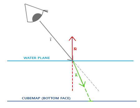
- 굴절 : material의 변화에 따라 빛의 방향이 달라지는 것
- 좌측의 그림은 굴절을 설명하고 있다
- view vector I, 법선 vector N, 굴절 vector R을 가지고 있다
: view vector의 방향은 약간 휘어지는데, 이 휘어진 vector R은 cubemap을 샘플링한
- 굴절은 GLSL의 refract 함수를 통해 쉽게 구현될 수 있다
: 법선 vector와 view 방향, 그리고 두 refactive indices 사이의 비율을 인자로 받는다
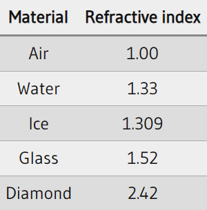
- 굴절 index는 material의 빛이 왜곡/휘어지는 정도를 결정한다
- 각 material들은 자신만의 고유한 refractive index를 가지고 있다
- 좌측 표는 가장 많이 쓰이는 refractive index를 제공한다
- 빛이 통과하는 두 material 사이의 비율을 계산하기 위해 이 refractive index들을 사용한다
: 우리의 경우에는 빛/view 광선이 공기에서 유리로 향하기 때문에 이 비율은 1.00/1.52 = 0.658이다
void main()
{
    float ratio = 1.00 / 1.52;
    vec3 I = normalize(Position - cameraPos);
    vec3 R = refract(I, normalize(Normal), ratio);
    FragColor = vec4(texture(skybox, R).rgb, 1.0);
}
- fragment를 수정해 refractive index를 수정해준다
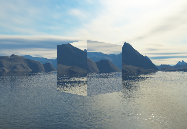
- 전체 프로그램 실행 결과
3. Dynamic Environment Maps
- Framebuffer를 사용하면 object로부터 6개의 다른 각도에 해당하는 scene의 texture를 생성할 수 있으며, 이를 반복문이 돌 때마다 cubemap에 저장할 수 있다
- 이후 이 cubemap을 현실적인 반사, 굴절면을 생성하기 위해 사용할 수 있고 이를 동적 환경 매핑이라고 부른다
: object의 주변 환경을 cubemap으로 동적으로 생성하고 이를 환경 매핑에 사용하기 때문이다
- 그러나 동적 환경 매핑은 environment map을 사용하는 object 당 6번 scene을 렌더링해야하므로 성능적으로 큰 단점을 가진다
'OpenGL Study' 카테고리의 다른 글
| OpenGL "Advanced GLSL" (0) | 2023.02.10 |
|---|---|
| OpenGL "Advanced Data" (0) | 2023.02.08 |
| OpenGL "FrameBuffers" (0) | 2023.02.07 |
| OpenGL "Face Culling" (0) | 2023.02.01 |
| OpenGL "Blending" (1) | 2023.02.01 |


